5G Millimeter Wave Performance Evaluation [Part 2] -- Outdoor Environmental Measurements, 5G Millimeter Wave Issues and Solutions
Quantitative understanding of its high-speed, high-capacity, and low-latency characteristics will be important for the widespread use of millimeter wave. In the second part, we will look at "5G Millimeter Wave Outdoor Environmental Measurements" and "5G Millimeter Wave Challenges and Solutions"....
2023/12/08
Posted on 2023/12/08
In order to promote the widespread use of millimeter wave, it is important to quantify its high-speed, high-capacity, and low-latency performance. In this article, specific experiments and measurements using 5G millimeter wave show that millimeter wave can achieve very high throughput and latency performance indoors and outdoors, and can be fully utilized indoors, even out of sight. In this second part, we will look at "5G Millimeter Wave Outdoor Environmental Measurements" and "5G Millimeter Wave Challenges and Solutions." (Click here for [Part 1)
Experimental and measurement results using 5G millimeter wave show that millimeter wave can achieve very high throughput and latency performance outdoors and can be fully utilized indoors even out of sight. Summaries of "5G Millimeter Wave Outdoor Environment Measurements" and "5G Millimeter Wave Challenges and Solutions," presented in the second part, are as follows.
Outdoor environment measurement of 5G millimeter wave
This is an introduction to outdoor measurements. Fixed-point and mobile measurements of throughput were conducted at a location in Tokyo where outdoor base stations are actually installed. The results showed that the outdoor base stations were able to form a millimeter wave communication area with a range of about 100m, and that even when the 5G millimeter wave area is not continuous and cannot be connected to 5G millimeter wave all the time, the average throughput, which fluctuates while moving, can be improved significantly compared to the case using sub6 improvement was found to be possible. This result indicates that 5G millimeter wave can provide high user benefits even in situations where area coverage is imperfect to some extent.
5G millimeter wave challenges and solutions.
We will present our work on the 5G millimeter wave challenge of supporting out-of-sight environments. We describe the research and development efforts underway in the areas of transponders, RIS, and the application of dielectric waveguides.
5G millimeter wave outdoor environmental measurements
Here we show 5G millimeter wave performance measured in an outdoor environment.
Outdoor environment measurement results of uplink throughput
Fig. 5-6 shows the results of a 5G millimeter wave communication performance benchmark study [2] conducted by Signals Research Group in Tokyo in April 2022. In this benchmark study, commercial smartphones supporting 5G millimeter wave were used to measure throughput, RSRP, and SINR by communicating with a 5G millimeter wave base station installed by an operator. Bandwidths of 400 MHz for the downlink and 200 MHz for the uplink are implemented, and the maximum throughput of 5G millimeter wave under these conditions is approximately over 2.4 Gbps for the downlink and over 400 Mbps for the uplink (2-layer MIMO and 64QAM modulation, respectively).
.
Fixed-point measurements of throughput were conducted in the vicinity of Shimbashi Station, and throughput measurements of 2 Gbps on the downlink and over 300 Mbps on the uplink were recorded. The distance between the terminal and the 5G millimeter wave base station at this time was confirmed to be about 115 m, indicating that millimeter wave can achieve high throughput even when the distance is about 100 m.
In practice, throughput varies greatly depending on location. Focusing on the uplink, 5G millimeter wave throughput was measured at fixed points in the area around Shimbashi Station (up to 400m from the Ginza exit of Shimbashi Station), and the results are shown below. Four millimeter wave base stations were installed in this area, each covering a different area, and it can be confirmed that throughput exceeding 150 Mbps was achieved in a wide area. In some locations where the communication environment was favorable, uplink throughput exceeded 250 Mbps in some cases.
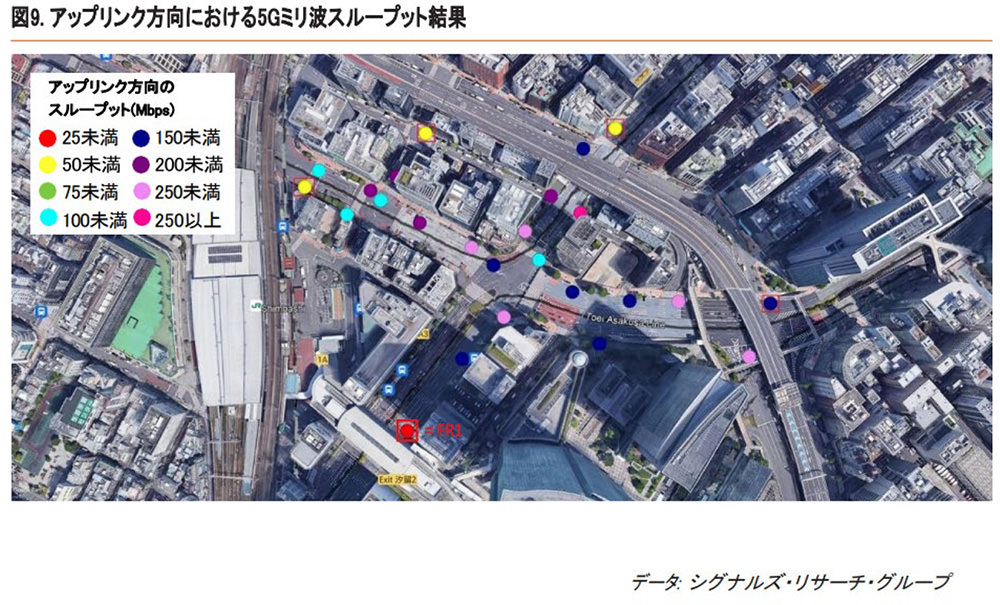
Fig. 5-6 Fixed-point measurement of 5G millimeter wave uplink throughput outdoors
<Movement measurement
Signals Research Group also measured the average uplink throughput when traveling on foot in the Tokyo station area; in Fig. 5-7, the rightmost graph shows the average throughput with 5G millimeter wave at the mobile station turned off and the center graph shows the average throughput with 5G millimeter wave at the mobile station turned on.
Even when 5G millimeter wave is turned on at a mobile station, communication is not always possible using millimeter wave, and because the line-of-sight environment and distance from the base station changes during movement, there are sections where millimeter wave communication is used and sections where it is not. The graph in the center shows the average throughput in such a situation where 5G millimeter wave is not used all the time. The leftmost graph shows the averaged throughput only for the segments where the 5G millimeter wave of the mobile station is turned on and communication by 5G millimeter wave is performed. In the sections where 5G millimeter wave is turned off or communication by 5G millimeter wave is not performed, the 5G sub6 frequency (frequency band n78) is used instead.
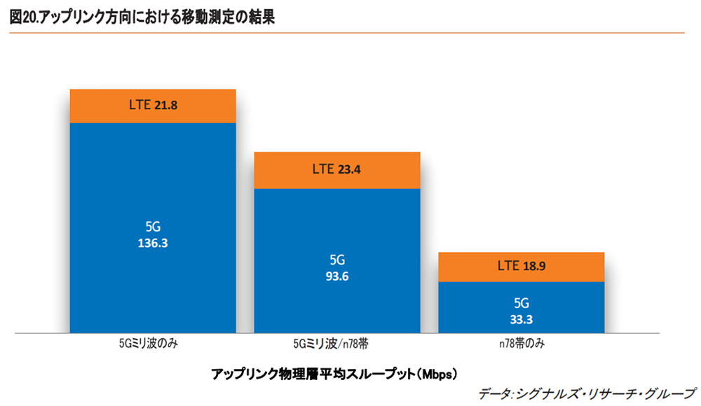
Fig. 5-7 5G millimeter wave uplink throughput mobility measurements outdoors
These results show that 5G millimeter wave can significantly improve the moving average throughput of the uplink. As mentioned earlier, the measurements in the center graph do not show that 5G millimeter wave is available all the time. Even so, it can be seen that an average of three times higher uplink throughput can be achieved than when only the 5G sub6 frequency band is used. 5G millimeter wave is sometimes said to be difficult to deploy in areas due to its linearity and attenuation characteristics, but these measurement results show that even in situations where area coverage is imperfect to some extent, high user benefits can be achieved. However, the measurement results show that high user benefits can be obtained even when area coverage is imperfect to some extent. The leftmost graph shows that throughput can be further improved if 5G millimeter wave deployment progresses further and 5G millimeter wave communication becomes possible almost all the time in the future.
On the other hand, in order to enable almost constant 5G millimeter wave communications, it is necessary to develop areas that are out of sight of the base station. In the next section, we will introduce some of these technologies.
Outdoor environment measurements of downlink throughput and latency
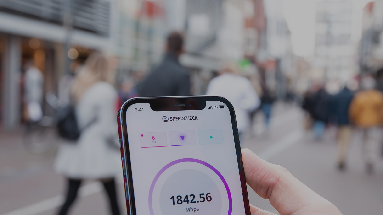
Next, we present the results of downlink and latency measurements of 5G millimeter wave commercial networks in an outdoor environment. Measurements were taken in November 2022 in Shibuya Ward, Tokyo, using actual commercial terminals. Throughput and latency were measured using the Ookla® Speedtest® application [3] while walking outdoors. The throughput and latency results obtained from the measurements are shown in Figs. 5-7 and 5-8. For comparison, the measured throughput and delay results using Sub6 and LTE are also shown.
Fig. 5-8 shows that the maximum downlink throughput is about 2 Gbps and the average throughput is about 1 Gbps when millimeter waves are used, which is about 4 times higher than Sub6 and 10 times higher than LTE. Figs. 5-9 show that the ping delay is about 15 ms when millimeter waves are used, which is about 1/3 of the delay of Sub6 and LTE.
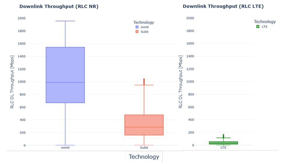
Fig. 5-8 5G millimeter wave downlink throughput mobility measurements outdoors
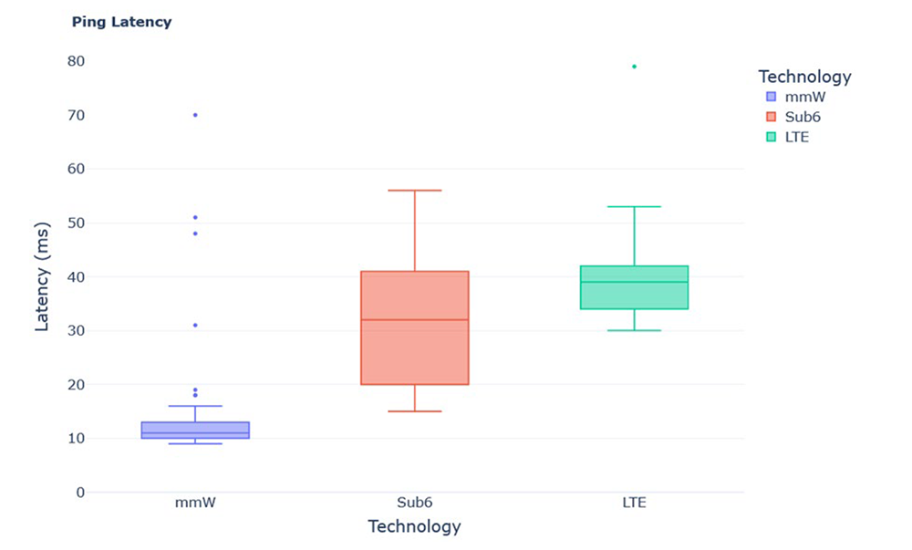
Fig. 5-9 5G millimeter wave downlink delay mobility measurement outdoors
In making this measurement, we also investigated the extent to which millimeter wave base stations cover the area. Specifically, we estimated the locations of millimeter wave base stations from the area maps of telecommunications carriers and recorded the distances to the above millimeter wave throughput and delay measurement points. As a result, we confirmed that the distance covered by millimeter wave base stations is at least 100 to 150 meters in most cases, and 200 to 250 meters on roads and alleys with good visibility.
5G millimeter wave challenges and solutions
Millimeter waves have strong straightness of radio waves, which makes their behavior closer to that of light, and their wraparound into the shadows of obstructions is smaller. Therefore, as mentioned in the previous section, the challenge is to create an area outside the line-of-sight from the base station. Although it is conceivable to install a large number of base stations in such areas, it is not economical, and more efficient area creation techniques are required. Therefore, a new wireless network topology is being considered that combines technologies such as relay stations, reflectors, and metasurfaces to construct new radio propagation paths according to the environment, and high-frequency transmission lines to avoid obstructions to create areas that are out of sight [4].
Repeaters
A relay station is a radio device that relays radio waves and extends the area by amplifying and re-radiating radio waves from base stations that have been weakened by shielding. For example, it consists of a donor unit that connects to the base station and a service unit that connects to the terminal, which are connected by a coaxial cable. The area can be constructed by installing the donor unit in the direction of the base station and the service unit in the direction in which the area is to be constructed.
The antenna is a beam-forming antenna, which allows the beam width and direction to be changed in the horizontal and vertical planes even after installation, enabling flexible area construction as needed. Output power of +37 dBm (5 W) is obtained for four waves (400 MHz bandwidth) with a signal bandwidth of 100 MHz. The antenna is equipped with a 64-element array antenna, and both horizontal and vertical plane directivity are reported to have 3 dB beamwidths from 15 to 80° and a beam steering range of ±30° [5-6].
Metamaterials/Metasurfaces Applications
In order to achieve a line-of-sight coverage in the millimeter wave band, it is necessary to control the propagation of radio waves either dynamically or adaptively according to the surrounding environment. One of the specific technologies to control radio propagation is RIS (Reconfigurable Intelligent Surface), which utilizes elemental technologies such as metamaterials and metasurfaces. RIS utilizes metamaterials and metasurfaces, which consist of a number of elements that scatter electromagnetic waves and whose scattering property distribution can be designed and controlled.
The metasurface can be fabricated in sheet form, so it can be installed according to the shape of the structure, and by controlling the reflection phase distribution with RIS, the propagation of the reflected wave can be controlled, for example, to maximize the received power. In the transparent dynamic metasurface, a transparent glass substrate is superimposed on a transparent metasurface substrate, and by moving the glass substrate slightly, three patterns can be dynamically controlled: a mode in which incident radio waves pass through, a mode in which some radio waves are transmitted and some are reflected, and a mode in which all radio waves are reflected.
In demonstration tests, it has achieved a transmittance of approximately -1.4 dB or better in the transmission mode and a transmittance of -10 dB or less in the reflection mode[7]. The transparent metasurface lens is in the form of a film that can be affixed to window glass, allowing radio waves passing through the window glass to be concentrated at a specific location indoors (hereinafter referred to as "focal point"). Therefore, by placing a repeater or reflector at the focal point, it is possible to area the inside of a building. In a demonstration experiment, it was confirmed that the received power at the focal point was improved by more than 24 dB compared to the case using ordinary transparent glass[7].
Dielectric waveguide applications
It is also necessary to assume cases where radio shields are moved. For example, a change in the layout of manufacturing equipment due to a change in the production line is applicable. The application of dielectric waveguides is being considered as a method of quickly and economically providing an outlook communication environment in response to changes in the propagation environment due to such changes. Dielectric waveguides are used as transmission lines for high-frequency bands, and propagation through them bypasses shielding and radiates radio waves to create out-of-sight areas. In addition, radio waves are radiated from a part of the dielectric waveguide, and the radiated radio waves make the surrounding area a communication area by radiated radio waves. The principle of radiating radio waves from a waveguide, or the application of a waveguide as an antenna, has been studied by bending the waveguide and radiating radio waves from the bending part, and by bringing the waveguide into contact with another dielectric material and radiating radio waves from another dielectric material part [8].
References
- 'Mobile mmWave Is Here - and Indoor Deployment Opportunities Abound,' Published by Fierce Wireless presented by Qualcomm
https://www.qualcomm.com/content/dam/qcomm-martech/dm-assets/documents/fierce_ebrief_-_mobile_mmwave_is_here_-_and_indoor_deployment_opportunities_abound_smaller.pdf ' - 5G Millimeter Waves Performed Well in Tokyo,' SIGNALS Research Group, June 2022.
https://www.qualcomm.com/content/dam/qcomm-martech/dm-assets/documents/SRG-Japan-5G-mmWave-Whitepaper.pdf - https://www.speedtest.net/apps
- "Advanced 5G and 6G, "NTT DOCOMO White Paper, Version 5.0,.
https://www.docomo.ne.jp/binary/pdf/corporate/technology/whitepaper_6g/DOCOMO_6G_White_PaperJP_20221116.pdf - Development of RF Repeater for 5G, Denko Giho, No. 53, 2021
- https://denkikogyo.co.jp/elec/product/mobile/l5g/
- "Transparent RIS technology for 5G evolution & 6G," NTT DCOMO Technical Journal, Vol. 29, No. 3, Oct 2021.
- "Pinching Antennas - Antenna Applications of Dielectric Waveguides," NTT DCOMO Technical Journal, Vol. 29, No. 3, Oct 2021.
The content of this article has been excerpted and edited based on the 5GMF White Paper "Advanced 5G with Millimeter Wave Penetration, Version 1.0" published by 5GMF on March 31, 2023. The white paper was updated to Version 2.0 on July 3, 2011. To view the full document, please click5GMF Web siteDownload from