5G Millimeter Wave Performance Evaluation [Part 1] -- Throughput and Latency Performance, Indoor Environment Measurement
In order to promote the widespread use of millimeter wave, it is important to quantify its high-speed, high-capacity, and low-latency performance. In this article, specific experimental and measurement results using 5G millimeter wave show that millimeter wave can achieve very high throughput and latency performance indoors and outdoors, and...
2023/12/07
Posted on 2023/12/07
In order to promote the widespread use of millimeter wave, it is important to quantify its high-speed, high-capacity, and low-latency performance. This article presents specific experimental and measurement results using 5G millimeter wave that show that millimeter wave can achieve very high throughput and latency performance indoors and outdoors, and can be fully utilized indoors, even out of sight. In this first part, we will look at "5G Millimeter Wave Throughput and Delay Performance Measurements" and "5G Millimeter Wave Indoor Environmental Measurements." (Click here for the second part.)
Experimental and measurement results using 5G millimeter wave show that millimeter wave can achieve very high throughput and delay performance outdoors and can be fully utilized indoors, even out of sight. Summaries of the "5G Millimeter Wave Throughput and Delay Performance Measurements" and "5G Millimeter Wave Indoor Environment Measurements" presented in the first part are as follows.
[Measurements of 5G millimeter wave throughput and delay performance (one-to-one communication, ideal environment)
Throughput and latency of one-to-one communication were measured by varying the receiving power in a radio proposal box environment with line-of-sight and no shielding or reflections. The results showed that throughput of more than 1 Gbps could be obtained and ping RTT of less than 7 ms could be maintained even in a low-order modulation scheme environment. These results indicate that 5G millimeter wave is suitable for a wide range of high-speed and low-latency services.
5G millimeter wave indoor environmental measurement
A 5G millimeter wave base station was installed in an actual indoor facility, and the throughput was measured at various different locations of mobile stations. As a result, it was found that not only high throughput could be achieved in the vicinity of the base station, but even in locations where there was shielding by pillars, the throughput was not significantly different from that in the vicinity of the base station. This result indicates that 5G millimeter wave can achieve high throughput over a wide range even in real indoor environments where some degree of shielding and distance between base stations and terminals are unavoidable.
5G millimeter wave throughput and delay performance measurements (one-to-one communication and ideal environment)
We measured the performance in an ideal environment for one-to-one communication using actual commercially available millimeter-wave-capable terminals and 5G millimeter-wave-capable pseudo-base stations. The millimeter wave-enabled pseudo base station was the Keysight E7515B, and the millimeter wave-enabled terminal was the SHARP AQUOS R7 (with Qualcomm Snapdragon 8 Gen 1). The pseudo base station and terminal were assumed to communicate using an LTE anchor in band 1 (2.1 GHz band) and a millimeter wave NR carrier (100 MHz x 4 cc for a total of 400 MHz) in band n257 (28 GHz band). The millimeter wave transmitter and receiver antennas of the terminal and the pseudo-base station are housed in a radio dark box, and the millimeter wave propagation distance is about 1.5 m. Various conditions such as path loss and terminal receiving power can be modified by changing the downlink power of the pseudo base station. The propagation environment is a clean line-of-sight (LOS) environment with almost no shielding or reflected waves.
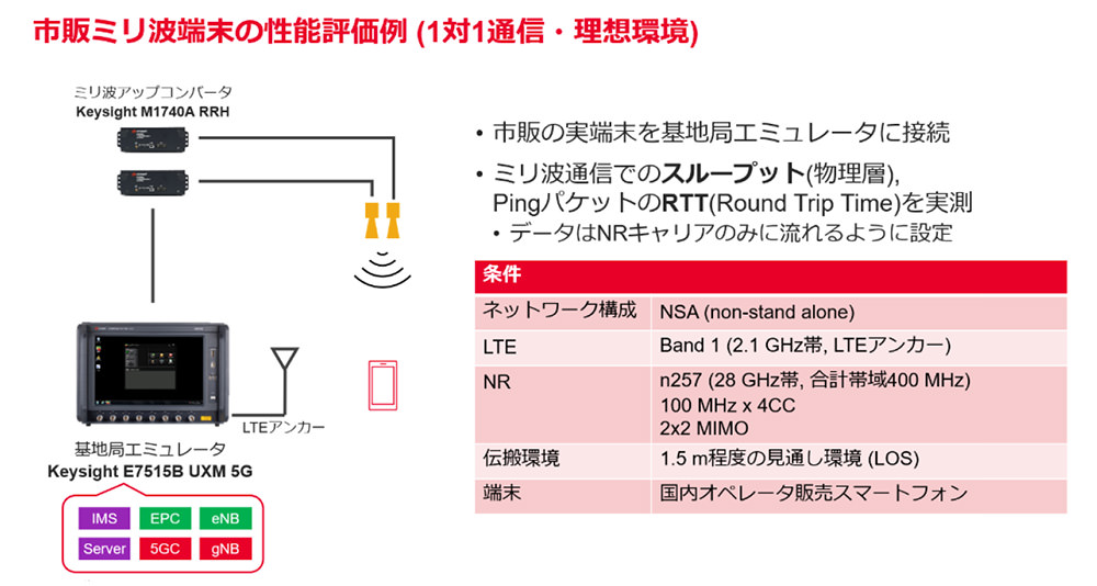
Fig. 5-1 Example of performance evaluation of a commercial millimeter wave terminal (provided by Keysight)
Downlink throughput evaluation
Fig. 5-2 shows the NR physical layer throughput when the downlink power of the pseudo base station is changed while the modulation and coding scheme (MCS: Modulation and coding scheme) of the millimeter wave carrier is fixed to 256QAM, 64QAM, 16QAM, and QPSK, respectively. Although this is an NSA configuration, the throughput measurements do not include the throughput on the LTE anchor side. With sufficiently high receive power (RSRP), throughput of over 3 Gbps was measured for 256 QAM. When the RSRP is -80 dBm or higher, almost error-free transmission can be achieved even at 256 QAM, and even when the RSRP is lowered to -110 dBm, error-free transmission can be achieved at 16 QAM, and throughput of more than 1 Gbps can be obtained stably. The wide frequency bandwidth of 400 MHz available for millimeter-wave transmission indicates that even low-order modulation can provide a high-speed communication environment.
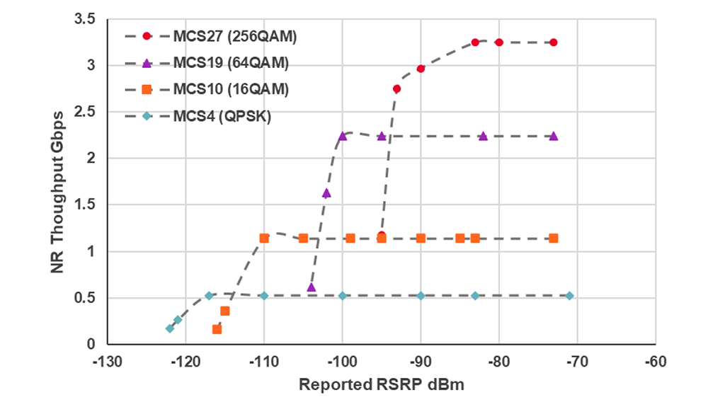
Fig. 5-2 5G millimeter wave terminal receive throughput
5G millimeter wave delay performance
Fig. 5-3 shows the NR physical layer throughput and the round trip time (RTT) delay due to ping packets when the millimeter wave pseudo base station's modulation scheme (MCS) is subjected to adaptive control (link adaptation) such that the downlink block error rate is approximately 10%. Fig. 5-3 shows the round trip time (RTT) of ping packets. When the downlink power is reduced, the average throughput gradually decreases from the peak due to the automatic change of modulation scheme by adaptive control. Similar to the results in the previous section, it was possible to maintain throughput of more than 1 Gbps up to an RSRP of about -110 dBm. At strong fields, the Ping RTT values ranged from 5.0 to 5.5 ms, but the increase in RTT values remained below 151 TP3T even as the RSRP decreased, and the RTT values were consistently below 6.5 ms in the RSRP range tested in this study. Millimeter wave systems can achieve inherently low latency communications regardless of the communication environment due to the benefits of wide subcarrier spacing and short time per slot, and the extremely short uplink and downlink switching period of the TDD pattern in millimeter wave.
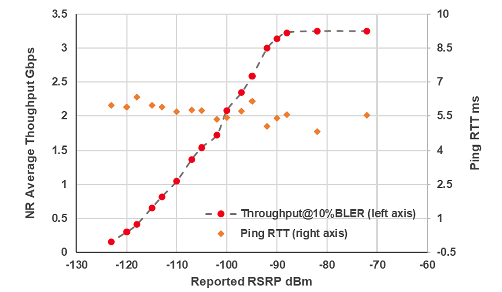
Fig. 5-3 5G millimeter wave terminal receive throughput and round-trip delay
The above results show that millimeter wave systems can provide a low latency and high throughput environment that can support a variety of use cases, and that millimeter wave-capable terminals already on the market have sufficient performance. In addition to the advantage of millimeter wave systems in providing high peak throughput, the measured data also shows that they can provide a stable low latency environment. This suggests that millimeter wave networks can be used for applications that require a stable low latency environment but do not necessarily require peak throughput (e.g., online gaming with moderate throughput and responsiveness requirements).
5G millimeter wave indoor environmental measurements
In this section, we present the results of 5G millimeter wave performance evaluation measured in an indoor environment. 5G millimeter wave base stations were set up in a corner of a 10 m x 20 m room shown in Fig. 5-4, and downlink throughput was measured at various locations (points A to F) in the room. Two-layer MIMO and 64QAM modulation were used on a millimeter wave NR carrier (100 MHz x 4cc for a total of 400 MHz) in band n257 (28 GHz band), DL:UL ratio = 4:1 for TDD operation, and the base station transmit power was 32 dBm. The average throughput for 5 seconds measured at each point was as follows.
Point A: 1666.54 Mbps
Point B: 1586.91 Mbps
Point C: 1851.24 Mbps
Point D: 1842.28 Mbps
Point E: 1602.87 Mbps
Point F: 1643.85 Mbps
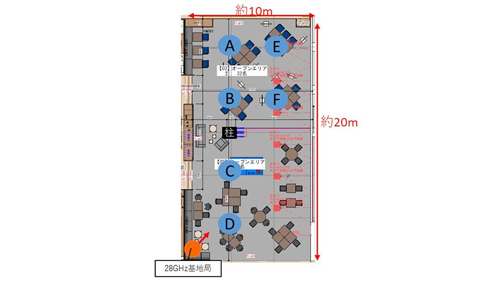
Fig. 5-4 Indoor measurement of 5G millimeter wave throughput
In the vicinity of the base station (points C/D), there is no shielding or attenuation, resulting in high throughput (>1.8 Gbps under the conditions and environment of this measurement). Points A/B/E/F are at a distance from the base station, and there is a pillar near the center of the room, so they are affected by a certain amount of shielding and attenuation compared to points C/D. Even so, it can be confirmed that throughputs in excess of 1.5 Gbps can be achieved at all points. This measurement result shows that even in a real indoor environment where a certain degree of shielding and distance between base stations and terminals are unavoidable, high throughput can be achieved over a wide range, including out-of-sight areas.
In airports, office buildings, and commercial facilities where radio waves from outdoor base stations are difficult to penetrate and the scale is relatively large, LTE/5G base stations and indoor wireless LAN access points, called DAS (Distributed Antenna System), are often installed indoors to provide communication services. In many cases, DAS (Distributed Antenna System) is installed indoors to provide communication services. In [1], the authors provide measurement results showing that 5G millimeter wave base stations attached to such DAS base stations and wireless LAN access points can provide wide coverage of such indoor facilities.
As an example, Fig. 5-5 shows a diagram visualizing the propagation loss (MPL: Maximum path-loss) from a 5G millimeter wave base station when a 5G millimeter wave base station is attached to an indoor base station or wireless LAN access point in an airport concourse [1]. Each 5G millimeter wave station is assumed to be equipped with 128 antenna elements per polarization and capable of forming 16 horizontal beams. It can be confirmed that the MPL is less than 115 dB in almost the entire area (99.71 TP3T area). The conditions in [1] indicate that a throughput of several Gbps can be obtained in this case in the area of 99.71 TP3T. In addition, [1] also shows similar results for airport concourses, convention centers, subway platforms, offices, and shopping stores.
Although it may be difficult to build a new 5G millimeter wave indoor base station separately when DAS and wireless LAN are already in place in a facility, the report in [1] indicates that if a 5G millimeter wave indoor base station can be attached to an existing indoor network, 5G millimeter wave services can be widely provided even in large facilities The report indicates that
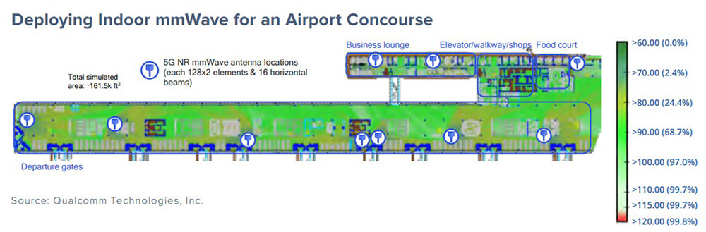
Fig. 5-5 Example of 5G millimeter wave base station installation at an airport and propagation loss measurement results
References
- 'Mobile mmWave Is Here - and Indoor Deployment Opportunities Abound,' Published by Fierce Wireless presented by Qualcomm
https://www.qualcomm.com/content/dam/qcomm-martech/dm-assets/documents/fierce_ebrief_-_mobile_mmwave_is_here_-_and_indoor_deployment_opportunities_abound_smaller.pdf ' - 5G Millimeter Waves Performed Well in Tokyo,' SIGNALS Research Group, June 2022.
https://www.qualcomm.com/content/dam/qcomm-martech/dm-assets/documents/SRG-Japan-5G-mmWave-Whitepaper.pdf - https://www.speedtest.net/apps
- "Advanced 5G and 6G, "NTT DOCOMO White Paper, Version 5.0,.
https://www.docomo.ne.jp/binary/pdf/corporate/technology/whitepaper_6g/DOCOMO_6G_White_PaperJP_20221116.pdf - Development of RF Repeater for 5G, Denko Giho, No. 53, 2021
- https://denkikogyo.co.jp/elec/product/mobile/l5g/
- "Transparent RIS technology for 5G evolution & 6G," NTT DCOMO Technical Journal, Vol. 29, No. 3, Oct 2021.
- "Pinching Antennas - Antenna Applications of Dielectric Waveguides," NTT DCOMO Technical Journal, Vol. 29, No. 3, Oct 2021.
The content of this article has been excerpted and edited based on the 5GMF White Paper "Advanced 5G with Millimeter Wave Penetration, Version 1.0" published by 5GMF on March 31, 2023. The white paper was updated to Version 2.0 on July 3, 2011. To view the full document, please click5GMF Web siteDownload from