Effective Technologies for Expanding Millimeter Wave Applications [Part 2] -- Device Technologies, Infrastructure Sharing, etc.
In the second part, we will look at the following five topics: millimeter wave device technology, infrastructure sharing, millimeter wave carrier aggregation (CA), sub6+ millimeter wave dual connectivity (DC), and High-Power UE (HPUE)....
2023/12/06
Posted on 2023/12/06
In this article,Challenges" for expanding millimeter wave use in 5GThis part of the report will provide a comprehensive overview of millimeter wave technologies that are considered to be effective in solving the issues of millimeter wave deployment introduced in Part 1, and millimeter wave-related technologies that have been specified or are under consideration for specification in 3GPP and other standardization bodies. The second part of the report will look at five of the eight millimeter wave technologies: millimeter wave device technology, infrastructure sharing, millimeter wave carrier aggregation (CA), sub6+ millimeter wave dual connectivity (DC), and High-Power UE (HPUE). (Click here for [Part 1)
Challenges still lie ahead for the widespread use of millimeter waves. Several technologies are considered effective in resolving these issues. This paper presents an overview of technologies that are considered effective in solving these issues and millimeter wave-related technologies that have been specified or are being considered for specification in standardization by 3GPP and other organizations.
Fig. 4-1 again summarizes the eight millimeter-wave technologies presented in this chapter and the challenges each technology solves.
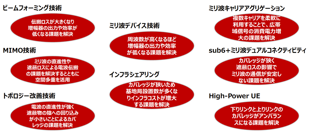
Fig. 4-1 Millimeter wave technology and challenges to be solved
Millimeter Wave Device Technology
This section discusses device-related technologies that can solve the problems of low amplifier output and efficiency at millimeter-waves. As shown in the figure, the output of amplifiers tends to decrease as the frequency increases, and at high frequencies above the 28-GHz band, the output of amplifiers made of CMOS and SiGe materials decreases significantly. Although it is possible to achieve higher output power even at millimeter wave by using GaN as the device material, the cost of GaN is higher than that of CMOS, and therefore, the current millimeter wave base stations use a combination of a multi-element array antenna and an amplifier made of CMOS or SiGe material. Therefore, if the cost of GaN decreases in the future, it will be possible to realize millimeter-wave base stations with various configurations other than the multi-element array antenna by using high-power amplifiers.
Next, we consider the issue of amplifier efficiency decreasing as frequency increases. sub6 significantly improves amplifier efficiency by applying DPD (Digital Pre-Distortion) to the Doherty amplifier, but DPD is not commonly used in millimeter wave, partly because the ACLR (Adjacent Channel Leakage Power) specification is loose. However, DPD is not generally used in millimeter wave due in part to loose ACLR (adjacent channel leakage power) specifications. However, there are sufficient advantages to applying DPD to millimeter-wave as well, such as reducing EMV (Error Vector Magnitude) and enabling 256QAM transmission by compensating signal distortion, and improving amplifier efficiency by reducing back-off. In millimeter-wave base stations with multi-element antennas, the circuit size and power consumption of DPDs increase because of the need to feed back broadband signals from a large number of amplifiers using a large number of high-speed ADCs. Therefore, taking advantage of the loose ACLR specification for millimeter wave, a technique to significantly reduce the circuit scale of the DPD by reducing the number of high-speed ADCs used for feedback is being considered [13].
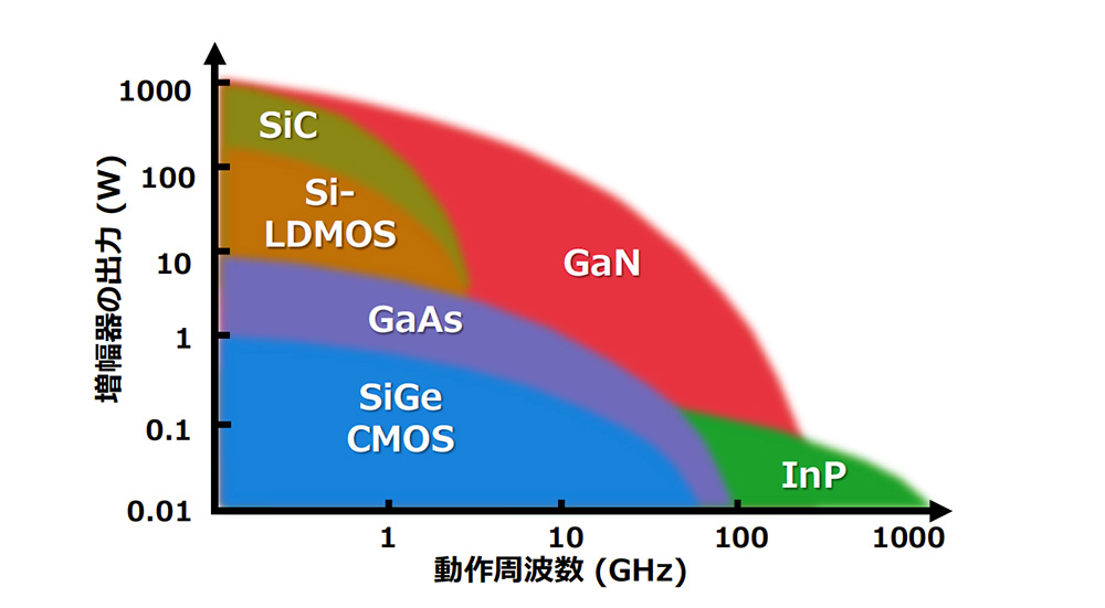
Fig. 4-5 Relationship between frequency and amplifier output
infrastructure sharing
Because of the narrow coverage of millimeter waves, it is necessary to install a very large number of base stations in order to build up an area over an area. Therefore, keeping the equipment and installation costs of base stations low is an important issue. Infrastructure sharing is considered to be one effective means of solving these issues [14].
As shown in Fig. 4-6, there are various forms of infrastructure sharing, including site sharing, in which towers and other installation sites are shared, antenna sharing, in which antenna facilities are shared, RU sharing, and base station sharing [15].
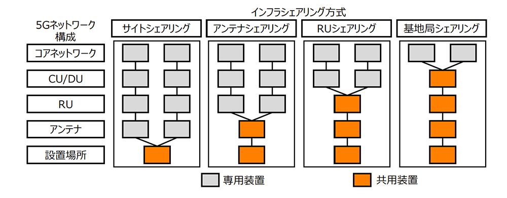
Fig. 4-6 Comparison of Infrastructure Sharing Methods
Infrastructure sharing in the form of using base stations and network facilities of other telecommunications carriers, such as roaming and MVNOs (Mobile Virtual Network Operators), is already in place. port, so antenna sharing is relatively easy to implement. On the other hand, millimeter waves are not suitable for antenna sharing due to their high transmission line loss, which increases the transmission distance between the amplifier and the antenna. Especially outdoors, where coverage must be ensured, sharing a base station or base station radio unit is suitable for millimeter wave, and its practical application is under consideration [15]. In high-frequency bands such as millimeter wave, where a wide bandwidth can be secured, a base station configuration in which the signal processing functions of the wireless base station are concentrated in a central station using an analog RoF (Radio-over-Fiber) and the extension station consisting of an antenna and amplifier is shared by multiple wireless systems is being considered [16 16]. This will improve the installation and economic efficiency by reducing the size and power consumption of the extension station.
Millimeter-wave carrier aggregation (CA)
In general, millimeter wave can communicate using a wider bandwidth compared to sub6. For example, in the 28 GHz band available in Japan, 400 MHz is allocated per 5G carrier, and up to 900 MHz of continuous frequency is available for local 5G. In many cases, instead of treating such a wide bandwidth as a single carrier, a form of carrier aggregation (CA) is applied in which multiple carriers with a bandwidth of 100 MHz or so are bundled together for communication [9]. In CA, it is also possible to use a different number of carriers for the downlink and uplink (Fig. 4-7). For example, the number of carriers can be controlled based on the required throughput to reduce power consumption of the mobile station. Millimeter wave CA has been standardized by 3GPP for all 5G millimeter wave frequency bands, including the 28 GHz band, and is an essential technology for millimeter wave operation.
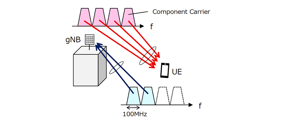
Fig. 4-7 Millimeter-wave carrier aggregation (CA)
sub6+ millimeter wave dual connectivity (DC)
In 5G, sub6 + millimeter-wave dual connectivity (DC), which uses the sub6 carrier as an anchor carrier for millimeter-wave communications and provides 5G services with simultaneous sub6 and millimeter-wave communications, is available [9, 17]. sub6 + millimeter-wave DC allows both sub6 and millimeter-wave communications simultaneously, achieving higher throughput than when millimeter wave is used alone. In addition, even in areas where millimeter wave does not provide continuous coverage or where millimeter wave communications are not stable, the sub6 frequency can be used to maintain the connection, thus preventing the occurrence of radio link failure (radio link failure) due to millimeter wave.
In sub6+millimeter wave DC, the radio access configuration in which sub6 is not a 5G carrier but an LTE carrier is called NSA (Non-Standalone), and it became an essential technology for early operation, especially in the early deployment of 5G (Fig. 4-8). sub6+millimeter wave DC (including NSA) has been standardized by 3GPP for implementation in various frequency combinations by operators in various countries. The sub6+ millimeter wave DC (including NSA) has been standardized by 3GPP so that it can be implemented in various frequency combinations of each country and operator [18], and is currently a widely used technology.
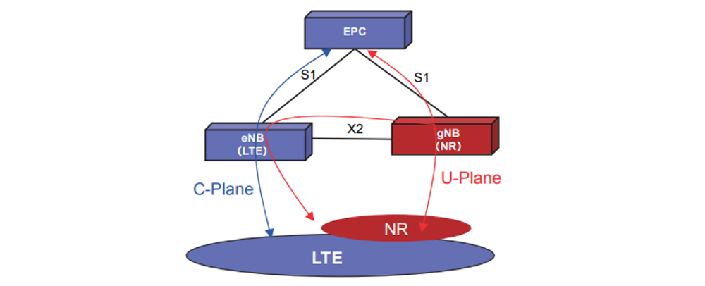
Fig. 4-8 LTE-NR Dual Connectivity connection image
High-Power UE (HPUE)
In millimeter wave and sub6 there is a maximum output power of mobile stations defined based on various aspects such as human protection and radio sharing. In general, the maximum power of a mobile station is often smaller than the maximum power of the base station, and the coverage imbalance between the downlink and uplink becomes an issue. To solve this problem, high-power mobile stations called HPUE (High-Power User Equipment) have been standardized [19]. HPUE can improve uplink coverage under the control of the base station by increasing the power to the extent that it does not cause problems in terms of human protection, etc. For example, Power Class 1 HPUE is a specification for fixed radio mobile stations and can output a maximum EIRP of 55 dBm.
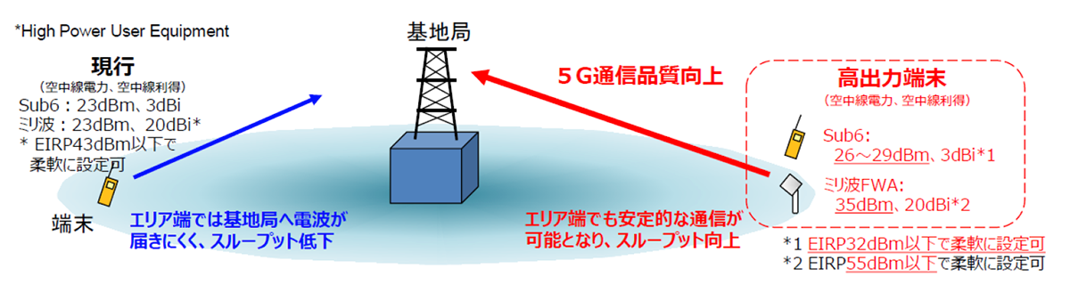
Fig. 4-9 Introduction of High Power Unit Extension (HPUE) [20].
References
- NTT DOCOMO Technical Journal, Vol. 23, No. 4, PP. 30-39, Jan. 2016.
https://www.docomo.ne.jp/binary/pdf/corporate/technology/rd/technical_journal/bn/vol23_4/vol23_4_005jp.pdf - Fujitsu, "RU Technologies," PP.4, 2023.
https://www.fujitsu.com/global/imagesgig5/RU-Technologies.pdf - K. Nishimori, et. al, "On the Transmission Method for Short-Range MIMO Communication," IEEE Trans. Vehicular Tech.
- M. Palaiologos, M. H. C. Garcia, R. A. Stirling-Gallacher and G. Caire, "Design of Robust LoS MIMO Systems with UCAs," 2021 IEEE 94th Vehicular Technology Conference (VTC2021-Fall), Norman, OK, USA, 2021, pp. 1-5.
- NTT DOCOMO Technical Journal, Vol. 15, No. 1, PP.55-59, Apr. 2007.
https://www.docomo.ne.jp/binary/pdf/corporate/technology/rd/technical_journal/bn/vol15_1/vol15_1_055jp.pdf - NEC, "Distributed MIMO in millimeter-wave frequency band to triple the number of simultaneous connections and transmission capacity under real office environment," , Jan. 2021.
https://jpn.nec.com/press/202101/20210125_01.html - KDDI R&D Laboratories, "World's First Successful Demonstration of Wireless Network Deployment Technology for Beyond 5G that Meets Individual Customer Needs," , Oct. 2021.
https://www.kddi-research.jp/newsrelease/2021/100701.html - NTT/DOCOMO/NEC, "World's First Successful Demonstration Experiment of Distributed MIMO in the 28-GHz Band to Keep Connected Without Worrying about Shielding," , Oct. 2022.
https://group.ntt/jp/newsrelease/2022/10/31/221031a.html - 3GPP TS 38.300, v17.3.0
- Denki Kogyo, "Repeater, Metamaterial Reflector (28 GHz band),"
https://denkikogyo.co.jp/elec/product/mobile/l5g/ - NTT DOCOMO Technical Journal, Vol. 29, No. 2, PP.15-39, July. 2021.
https://www.docomo.ne.jp/binary/pdf/corporate/technology/rd/technical_journal/bn/vol29_2/vol29_2_004jp.pdf - NTT DOCOMO Technical Journal, Vol. 29, No. 2, PP.7-12, July. 2021.
https://www.docomo.ne.jp/binary/pdf/corporate/technology/rd/technical_journal/bn/vol29_3/vol29_3_003jp.pdf - T. Ota, et.al, "An Experimental Study on Multibeam Digital Predistorter with Intercarrier Interference Suppression," in Proc. IEEE VTC2022-Fall, 2022.
- TEPCO Power Grid, "Final summary of the opinion exchange meeting for the future 5G base station," Feb. 2022.
https://www.tepco.co.jp/pg/company/press-information/information/2022/pdf/220204a.pdf - JTOWER, "JTOWER and Foxconn Sign Agreement for Development of 5G Millimeter Wave Compatible Shared Radio," Apr. 2022.
https://www.jtower.co.jp/2022/14516/ - NTT, "Efficient Accommodation of Various High Frequency Band Radio Systems Using Analog RoF," , Mar. 2020.
https://www.rd.ntt/research/JN20200315_h.html - NTT DOCOMO Technical Journal, Vol. 28, No. 2, PP.24-38, July 2020.
https://www.docomo.ne.jp/binary/pdf/corporate/technology/rd/technical_journal/bn/vol28_2/vol28_2_005jp.pdf - 3GPP TS 38.101-3, v17.8.0
- 3GPP TS 38.101-2, v17.8.0
- Information and Communications Council, Information and Communications Technology Subcommittee, New Generation Mobile Communications Systems Committee (25th Meeting), Document 25-2 "Technical Conditions for Relay Stations and High Power Terminals for Expanded Use of 5G, etc.
The content of this article has been excerpted and edited based on the 5GMF White Paper "Advanced 5G with Millimeter Wave Penetration, Version 1.0" published by 5GMF on March 31, 2023. The white paper was updated to Version 2.0 on July 3, 2011. To view the full document, please click5GMF Web siteDownload from